Thermal Barrier Coatings: The Invisible Shield Protecting Turbine Blades at 1,600°C | Safe Fly Aviation
Thermal Barrier Coatings: The Invisible Shield at 1,600°C
Protecting turbine blades at temperatures hotter than lava
Welcome to one of Safe Fly Aviation's most technically intensive deep dives yet. Today, we're exploring one of aerospace engineering's most remarkable — yet largely invisible — innovations: thermal barrier coatings (TBCs). These gossamer-thin ceramic layers, typically just 100–500 micrometres thick, roughly the width of a few human hairs, enable modern jet engines to operate at temperatures that would instantly melt unprotected metal.
To put this in perspective: lava from volcanic eruptions typically reaches 700–1,200°C. Modern high-pressure turbine blades operate in gas streams that can exceed 1,600°C — temperatures at which the nickel-based superalloy substrate would lose structural integrity within seconds without protection. Yet with thermal barrier coatings, these same blades survive thousands of flight cycles, each involving brutal thermal shocks from ambient to peak temperature and back.
This guide takes you from the fundamental materials science of TBCs through to cutting-edge developments in gadolinium zirconate and multi-layer architectures. We examine failure mechanisms, explore manufacturing processes, and look at how these coatings have helped extend turbine blade service life whilst allowing engines to run hotter and more efficiently.
Whether you're an aerospace engineer, materials scientist, maintenance technician, or aviation enthusiast, this article illuminates the invisible technology that quite literally keeps modern aviation aloft.

1. The Fundamental Challenge: Why We Need TBCs
The Thermodynamic Imperative
Modern jet engine efficiency is governed by the Brayton thermodynamic cycle, where efficiency (η) increases with the pressure ratio and turbine inlet temperature (TIT). The relationship is approximately:
Brayton Cycle Efficiency
η ≈ 1 − (1/r)(γ−1)/γ
Where: r = pressure ratio, γ = specific heat ratio (≈1.4 for air)
But: higher TIT dramatically improves performance beyond this basic equation.
- Every 100°C increase in TIT yields roughly 10–12% more thrust
- Or equivalently: 3–4% improvement in specific fuel consumption (SFC)
- Modern engines target a TIT of 1,600–1,700°C, well above the roughly 1,000–1,100°C typical of high-bypass turbofans several decades ago
The Material Limitation
The problem? The best nickel-based superalloys (like CMSX-4, René N5, or Inconel 738) have melting points around 1,300–1,400°C — independently confirmed against published materials-science references — and they begin losing significant creep strength above 1,000–1,050°C. Without thermal protection, turbine blades would fail almost immediately in the gas path.
Without a coating and internal cooling working together, turbine blades would:
- Creep rapidly: permanent deformation under stress at elevated temperature
- Oxidise catastrophically: react with oxygen, forming thick, non-protective oxide scales
- Melt locally: particularly at leading edges and tips, where heat flux is highest
- Fail within hours: rather than the required 10,000–25,000 flight cycles
The Multi-Pronged Solution
Modern turbine blades employ a three-part thermal protection strategy:
Whilst internal cooling does the heavy lifting, TBCs are the enabling technology that allows turbine inlet temperatures to push beyond what cooling alone can achieve. Without TBCs, the engine efficiency gains of the past few decades simply wouldn't exist.
Expert TBC Inspection & Repair Services
Safe Fly Aviation offers comprehensive thermal barrier coating assessment, non-destructive testing, and certified repair services. Extend your turbine blade life and optimise engine performance.
Schedule an Inspection2. TBC Architecture: The Four-Layer System

The Standard TBC System
Modern thermal barrier coatings are not single-layer structures but sophisticated multi-layer systems, each component serving a specific function — a structure confirmed across published TBC literature including the Wikipedia summary of the field: substrate, bond coat, thermally grown oxide, and ceramic top coat.
| Layer | Material | Thickness | Primary Function |
|---|---|---|---|
| Substrate | Ni-based superalloy (CMSX-4, René N5) | ~3–5 mm | Load-bearing structural component |
| Bond Coat | MCrAlY or Pt-aluminide | 75–150 µm | Adhesion, oxidation protection |
| TGO (Thermally Grown Oxide) | α-Al₂O₃ (alumina) | 1–10 µm (grows with time) | Oxygen diffusion barrier |
| Top Coat (Ceramic) | 7–8% YSZ or gadolinium zirconate | 100–500 µm | Thermal insulation, strain tolerance |
Layer 1: The Superalloy Substrate
The foundation is a single-crystal or directionally-solidified nickel-based superalloy, optimised for high-temperature creep resistance. Common alloys include:
- CMSX-4: second-generation single-crystal alloy, roughly 9% rhenium, 6% chromium, 6.5% aluminium, 6% tungsten
- René N5: first/second-generation, roughly 3% rhenium, excellent castability
- Inconel 738: polycrystalline, widely used in older engines and stationary components
Layer 2: The Bond Coat
The bond coat serves three critical functions: mechanical bonding between ceramic and metal, oxidation protection, and thermal expansion matching. Two main types dominate:
Bond Coat Types
MCrAlY Coatings (M = Ni, Co, or NiCo):
- Composition: nickel or cobalt base with 15–25% chromium, 8–12% aluminium, 0.3–1.0% yttrium
- Applied via plasma spray, HVOF (high-velocity oxy-fuel), or EB-PVD
- Excellent oxidation resistance, moderate thermal expansion match
- Typical thickness: 100–150 µm
Platinum-Aluminide Coatings:
- Two-step process: electroplate platinum (5–10 µm), then aluminise via chemical vapour deposition (CVD)
- Forms β-NiAl phase with platinum dissolved in solid solution
- Superior alumina formation kinetics, better TGO quality
- Typical thickness: 50–80 µm (diffusion zone extends deeper)
Layer 3: The Thermally Grown Oxide (TGO)
The TGO is not intentionally applied — it forms naturally during engine operation as aluminium from the bond coat reacts with oxygen diffusing through the ceramic top coat. Ideally, this forms a slow-growing, protective α-alumina (α-Al₂O₃) layer.
Layer 4: The Ceramic Top Coat
The ceramic top coat is the star of the show — providing the critical thermal insulation. The requirements are demanding:
- Low thermal conductivity: roughly 1–2 W/m·K, versus roughly 20 W/m·K for superalloys
- High melting point: above 2,500°C, to survive peak temperatures
- Thermal expansion match: close to the superalloy (roughly 10–12 × 10−6/K), to minimise stress
- Phase stability: no destructive phase transformations during thermal cycling
- Strain tolerance: accommodate differential thermal expansion without cracking
- CMAS resistance: resist attack by molten calcium-magnesium-alumino-silicate deposits
For more than 40 years, one material has dominated: yttria-stabilised zirconia (YSZ).
Advanced TBC Analysis & Materials Testing
Our laboratory partners provide comprehensive TBC characterisation, failure analysis, and remaining-life assessment using industry-standard diagnostic techniques.
Learn More About Our Services3. Yttria-Stabilised Zirconia (YSZ): The Industry Standard
What Is YSZ and Why Does It Work?
Pure zirconia (ZrO₂) undergoes a destructive phase transformation at around 1,170°C, from monoclinic to tetragonal crystal structure, accompanied by a roughly 3–5% volume change. Repeated cycling through this transformation would quickly crack any coating. The solution: add 6.5–8 weight% yttria (Y₂O₃), which stabilises the cubic fluorite crystal structure across the entire operating temperature range. Independent materials-science references confirm YSZ's phase-stability ceiling sits at around 1,200°C, above which phase decomposition begins — the same limitation this article's later sections build on.
YSZ Material Properties
| Property | Value | Significance |
|---|---|---|
| Thermal Conductivity | 1.5–2.3 W/m·K @ 1,000°C | Roughly 10× lower than superalloys |
| Thermal Expansion | 10–11 × 10−6/K | Good match to superalloys (11–13) |
| Melting Point | ~2,680°C | Far exceeds operating temperatures |
| Young's Modulus | 50–80 GPa (porous coating) | Lower stiffness → better strain tolerance |
| Density | 5.5–6.0 g/cm³ | Relatively low for ceramics |
Manufacturing YSZ Coatings: APS vs EB-PVD
Two primary methods dominate TBC application, each with distinct microstructures and properties:

Atmospheric Plasma Spray (APS)
Process: YSZ powder particles (typically 20–80 µm diameter) are injected into a plasma torch generating temperatures of 10,000–15,000 K. Molten/semi-molten particles impact the blade surface at roughly 100–300 m/s, flattening into splats and building up layer by layer.
Microstructure: lamellar (layered) structure with extensive porosity (10–20%), microcracks, and inter-splat boundaries. Thermal conductivity: roughly 1.0–1.5 W/m·K.
Advantages:
- Cost-effective (equipment roughly £100,000–500,000, versus roughly £5–10 million for EB-PVD)
- High deposition rates (100–500 µm/hr)
- Suitable for complex geometries
- Low thermal conductivity, aided by porosity
Disadvantages:
- Lower strain tolerance → more prone to spallation under thermal cycling
- Rougher surface finish
- Reduced durability versus EB-PVD
Electron Beam Physical Vapour Deposition (EB-PVD)
Process: in a vacuum chamber (roughly 10−3 mbar), an electron beam melts and evaporates YSZ ingots. Vapour atoms condense on the blade substrate, nucleating and growing as columnar grains perpendicular to the surface.
Microstructure: distinctive columnar structure (columns roughly 1–10 µm diameter) with inter-columnar gaps providing strain compliance. Thermal conductivity: roughly 1.5–2.0 W/m·K (higher, due to denser columns).
Advantages:
- Superior strain tolerance → roughly 2–3× longer thermal-cycling life
- Smoother surface (better aerodynamic performance)
- Better erosion resistance
- Preferred for rotating turbine blades (highest thermal-cycling severity)
Disadvantages:
- Extremely expensive capital equipment and operating costs
- Slower deposition (20–100 µm/hr)
- Line-of-sight limitation (shadowing on complex geometries)
- Higher thermal conductivity than APS
Why YSZ Dominates (Despite Its Limitations)
YSZ remains the overwhelming choice for production TBCs because:
- Proven track record: billions of flight hours across thousands of engine types
- Manufacturing maturity: well-understood deposition processes and quality control
- Cost-effectiveness: raw materials (zirconia, yttria) are relatively affordable
- Repairability: established strip-and-recoat procedures for engine overhaul
- "Good enough" performance: meets requirements for turbine inlet temperatures up to roughly 1,500–1,600°C
However, YSZ has fundamental limitations that become critical as turbine inlet temperatures push towards 1,700°C and beyond.
4. TBC Failure Modes: When Coatings Go Wrong

Understanding TBC Degradation
Thermal barrier coatings don't fail suddenly — they degrade progressively through several mechanisms, often acting together. Understanding these failure modes is critical for predictive maintenance and life-extension strategies.
Spallation
Mechanism: delamination and loss of the ceramic top coat, typically at the TGO/bond coat interface. Caused by strain-energy accumulation from TGO growth, thermal expansion mismatch, and thermal cycling.
Typical onset: 5,000–15,000 thermal cycles (EB-PVD); 2,000–8,000 cycles (APS)
TGO Thickening
Mechanism: the thermally grown oxide layer grows with time, increasing from roughly 1 µm to 8–10 µm. Growth strains accumulate, eventually exceeding coating adhesion strength.
Critical thickness: spallation risk increases sharply once TGO exceeds roughly 8–10 µm
CMAS Attack
Mechanism: calcium-magnesium-alumino-silicate (CMAS) deposits from ingested sand or volcanic ash melt at roughly 1,150–1,240°C, infiltrating YSZ porosity. On cooling, CMAS solidifies, eliminating strain tolerance and causing spallation.
Onset: a single CMAS infiltration event can cause rapid, localised failure
Sintering
Mechanism: at elevated temperatures, YSZ pores gradually close (sinter), increasing thermal conductivity and stiffness, and reducing strain tolerance.
Effect: roughly 20–50% conductivity increase after 5,000–10,000 hours above 1,200°C
Erosion
Mechanism: particle impacts (dust, sand, unburned carbon) physically remove coating material, particularly at leading edges.
Rate: highly variable; roughly 10–50 µm loss per 1,000 flight hours in dusty environments
Foreign Object Damage
Mechanism: larger debris impacts cause localised coating delamination and substrate damage.
Criticality: can initiate accelerated failure propagation from the damaged region
The Spallation Problem: Life-Limiting Failure Mode
Spallation — the delamination and loss of the ceramic top coat — is the primary life-limiting failure mode for TBCs. The physics involves complex stress states:
The Spallation Mechanism
Step 1: TGO Growth – as the TGO thickens, volumetric growth strains develop. Since the TGO is constrained between bond coat and ceramic, compressive stresses build up (roughly 3–6 GPa).
Step 2: Stress Relaxation – at operating temperature, these stresses partially relax through creep. But on cooling, the TGO contracts differently to the surrounding materials.
Step 3: Tensile Stress Development – during cool-down, tensile stresses develop perpendicular to the interface. Once these exceed the interface fracture toughness (roughly 50–150 J/m²), cracks nucleate.
Step 4: Propagation – cracks propagate laterally along the TGO/bond coat interface. When the cracked area reaches a critical size (roughly 1–5 mm²), stored strain energy drives spallation.
CMAS: The Desert Enemy
CMAS (calcium-magnesium-alumino-silicate) attack is one of TBC's most insidious failure modes. The phenomenon works as follows:
- Ingestion: aircraft operating in desert environments, or near volcanic eruptions, ingest fine silicate particles (sand, dust, volcanic ash)
- Melting: these particles deposit on turbine blades and melt at roughly 1,150–1,240°C — well within operating temperatures
- Infiltration: molten CMAS wicks into YSZ porosity and inter-columnar gaps via capillary action, penetrating 50–200 µm within minutes
- Chemical reaction: CMAS reacts with YSZ, destabilising the cubic phase and forming monoclinic ZrO₂ — a destructive phase transformation
- Solidification: on cooling, CMAS solidifies, locking the coating in a rigid state with no strain compliance
- Catastrophic failure: the next thermal cycle generates stresses that can immediately spall the infiltrated region
Quantifying TBC Life: Empirical Models
Predicting TBC lifespan involves empirical correlations built from extensive engine testing. These are conservative, order-of-magnitude industry figures rather than a single universal standard:
| Application | Coating Type | Typical Life (Cycles) | Life (Hours) |
|---|---|---|---|
| High-Pressure Turbine Blades | EB-PVD YSZ | 10,000–15,000 | 15,000–25,000 |
| High-Pressure Turbine Vanes | APS YSZ | 15,000–25,000 | 25,000–40,000 |
| Low-Pressure Turbine | APS YSZ | 20,000–30,000 | 30,000–50,000 |
| Combustor Liners | APS YSZ | 10,000–20,000 | 20,000–35,000 |
Note: these are conservative estimates. Actual life depends on operating conditions — TIT, thermal-cycling severity, CMAS exposure, and maintenance quality. Safe Fly Aviation's engineering team also covers related high-temperature components such as combustor liners in a companion deep dive.
Stay Informed on TBC Technology Advances
Explore more of Safe Fly Aviation's technical deep dives on engine materials science, coatings technology, and maintenance best practice.
Explore More Engine Insights5. Beyond YSZ: Gadolinium Zirconate and Multi-Layer Architectures

YSZ's Fundamental Limitations
As turbine inlet temperatures push towards 1,700°C and beyond, YSZ's shortcomings become critical:
- Sintering above 1,200°C: thermal conductivity increases roughly 30–50% after prolonged exposure
- Phase instability: above 1,200°C, yttria slowly segregates, destabilising the cubic phase
- CMAS susceptibility: YSZ readily dissolves in molten CMAS, losing all protective function
- Limited temperature capability: an effective ceiling of roughly 1,500–1,600°C surface temperature
The search for "YSZ 2.0" has focused on materials with higher temperature capability, better CMAS resistance, and lower thermal conductivity.
Gadolinium Zirconate: The Leading Candidate
Gadolinium zirconate (Gd₂Zr₂O₂) has emerged as the most promising next-generation TBC material, with several compelling advantages:
Gadolinium Zirconate Properties
| Property | YSZ | Gd₂Zr₂O₂ | Advantage |
|---|---|---|---|
| Thermal Conductivity (1,000°C) | 1.8–2.3 W/m·K | 1.2–1.5 W/m·K | ~35% lower |
| Phase Stability | Stable to ~1,200°C | Stable above 1,500°C | +300°C margin |
| CMAS Resistance | Poor (dissolves readily) | Excellent (forms stable apatite) | ~10× slower penetration |
| Thermal Expansion | 10–11 × 10−6/K | 9–10 × 10−6/K | Slightly lower (trade-off) |
| Sintering Resistance | Moderate | Superior | Maintains porosity longer |
The CMAS Solution: Reactive Barrier Formation
Gadolinium zirconate's standout feature is its CMAS resistance. Unlike YSZ, which dissolves, Gd₂Zr₂O₂ reacts with molten CMAS to form calcium rare-earth silicate apatite (Ca₂RE₈(SiO₄)₆O₂) — a high-melting-point (roughly 1,550°C), chemically stable phase that acts as a self-sealing barrier:
Challenges with Gadolinium Zirconate
Despite superior properties, Gd₂Zr₂O₂ faces adoption challenges:
Gadolinium Zirconate Hurdles
- Thermal expansion mismatch: lower CTE (roughly 9 × 10⁻⁶/K) versus the superalloy (roughly 13 × 10−6/K) increases thermal stress
- Lower toughness: Gd₂Zr₂O₂ is more brittle than YSZ, increasing spallation risk under mechanical loading
- Higher cost: gadolinium oxide is significantly more expensive than yttrium oxide
- Limited manufacturing experience: deposition parameters are not as mature as for YSZ
- Compatibility: requires development of compatible bond coats and deposition processes
The Multi-Layer Solution
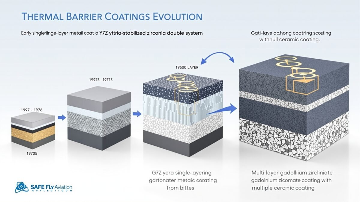
Rather than wholesale replacement of YSZ, the industry is converging on multi-layer or graded TBC systems that exploit the best properties of multiple materials:
Advanced Multi-Layer TBC Architecture
Layer 1 (Bottom): YSZ (50–100 µm) – provides thermal expansion match to the bond coat, with proven reliability
Layer 2 (Transition): YSZ/Gd₂Zr₂O₂ gradient (50–100 µm) – a gradual composition transition minimising interface stress
Layer 3 (Top): Gd₂Zr₂O₂ (100–200 µm) – CMAS resistance, low conductivity, high-temperature stability
Optional Layer 4: dense gadolinia top seal (roughly 10 µm) – additional CMAS barrier, erosion resistance
Other Advanced TBC Materials Under Development
The research pipeline includes several exotic alternatives:
- Rare-earth zirconates (La₂Zr₂O₂, Nd₂Zr₂O₂): similar to gadolinium zirconate, with varying thermal expansion and CMAS-resistance trade-offs
- Perovskites (SrZrO₃, BaZrO₃): ultra-low thermal conductivity (roughly 1.0 W/m·K) but challenging phase stability
- Pyrochlores with multiple dopants: complex compositions (Gd₂Zr₂O₂ + YSZ + Al₂O₃) tailored for specific properties
- MAX phase coatings: ternary carbides/nitrides combining ceramic and metallic properties, with excellent damage tolerance
- Rare-earth phosphates (YPO₄, GdPO₄): extremely low thermal expansion (roughly 2 × 10⁻⁶/K), with potential for ultra-thick coatings
Advanced Coatings Consultation
Considering a next-generation TBC upgrade path for your fleet? Safe Fly Aviation's engineering advisory team can help you evaluate the options.
Talk to Our Engineering Team6. The Future of TBCs: Enabling Next-Generation Propulsion
Turbine Inlet Temperatures: The March Continues
Historical trends show TIT increasing at roughly 10–15°C per year since the 1970s — a widely cited industry rule of thumb rather than a single precise figure, consistent with independently confirmed data points showing modern high-performance aviation engines now exceeding 1,650°C. Extrapolating forward:
- Current state of the art (2025–2026): roughly 1,600–1,650°C (GE9X, Pratt & Whitney GTF, Rolls-Royce UltraFan)
- 2030 targets: roughly 1,700–1,750°C (next-generation narrowbody engines)
- 2040 aspirations: roughly 1,800–1,900°C (revolutionary propulsion concepts)
At these temperatures, even advanced TBCs will be stretched to their limits. Multiple enabling technologies must converge:
Future TBC Requirements
- Enhanced cooling: advanced internal cooling geometries (additive manufacturing enables complex passages), potentially transpiration cooling through porous TBCs
- Lower-conductivity coatings: targeting below 1.0 W/m·K through engineered porosity and phonon-scattering nanostructures
- Superior CMAS resistance: increasingly important as desert and dusty-environment operations expand
- Environmental barrier coatings (EBCs): protect the underlying TBC from water-vapour attack at extreme temperatures
- Self-healing mechanisms: coatings that autonomously repair microcrack damage during operation
Sustainable Aviation and Hydrogen Propulsion
The shift towards sustainable aviation fuels (SAFs) and hydrogen poses new TBC challenges:
Advanced Manufacturing: The Enabler
Next-generation TBCs will leverage cutting-edge manufacturing:
- Solution precursor plasma spray (SPPS): deposits coatings from liquid feedstock, enabling complex compositions and finer microstructures
- Suspension plasma spray (SPS): nanoscale particles create coatings with an ultra-fine columnar structure and engineered porosity
- Laser-assisted deposition: precise local heating enables graded compositions and tailored microstructures
- Additive manufacturing integration: direct printing of TBC-integrated blade structures (substrate and coating in one process)
- Atomic layer deposition (ALD): nanoscale-precise coatings for sealing and environmental protection
Inspection and Remaining Life Assessment
As TBCs become more critical and complex, non-destructive inspection advances are crucial:
| Technique | Measures | Capability | Limitation |
|---|---|---|---|
| Infrared Thermography | Delaminated areas (thermal contrast) | Rapid, large-area coverage | Detects only advanced damage |
| Eddy Current | TBC thickness, bond-coat oxidation | Quantitative thickness measurement | Requires calibration, conductive substrate |
| Ultrasonic | Delamination, coating adhesion | High sensitivity to interfaces | Complex signal interpretation |
| Laser-Induced Fluorescence | TGO thickness, phase composition | Non-contact, chemical specificity | Research tool, not production-ready |
| Terahertz Imaging | Layer thickness, porosity, delamination | Penetrates ceramics, 3D imaging | Expensive, slow |
The Economic Imperative
TBC technology delivers substantial economic value:
Frequently Asked Questions
What is a thermal barrier coating and why do jet engines need one?
A thermal barrier coating (TBC) is a thin ceramic layer, typically 100–500 micrometres thick, sprayed or vapour-deposited onto turbine blades and vanes. It insulates the underlying nickel-based superalloy from combustion gases that can exceed 1,600°C — hotter than the alloy's own melting point of roughly 1,300–1,400°C. Combined with internal air cooling, the TBC reduces the metal surface temperature by around 150–200°C, which is what allows the blade to survive at all.
How thick is a thermal barrier coating on a turbine blade?
A typical aerospace TBC topcoat is 100–500 micrometres thick, roughly the width of a few human hairs, sitting on top of a 75–150 micrometre metallic bond coat. Despite being gossamer-thin, this ceramic layer is what makes the difference between a blade surviving thousands of flight cycles and failing within hours.
What is yttria-stabilised zirconia (YSZ) and why is it used in coatings?
Yttria-stabilised zirconia (YSZ) is zirconium dioxide (ZrO₂) stabilised with 6.5–8 weight% yttria (Y₂O₃), which prevents the destructive volume-changing phase transformation pure zirconia undergoes on cooling. YSZ has been the industry-standard TBC topcoat material for more than 40 years thanks to its low thermal conductivity, good thermal expansion match to superalloys, and a mature, cost-effective manufacturing base.
What is the difference between APS and EB-PVD coating methods?
Atmospheric Plasma Spray (APS) melts ceramic powder in a plasma torch and sprays it onto the part, producing a porous, lamellar coating that is relatively inexpensive and fast to apply. Electron Beam Physical Vapour Deposition (EB-PVD) evaporates ceramic in a vacuum chamber so it condenses as columnar grains, giving superior strain tolerance and roughly 2–3 times longer thermal-cycling life, at far higher equipment cost. EB-PVD is generally preferred for rotating turbine blades, while APS is widely used on vanes, combustor liners, and other static parts.
Why do thermal barrier coatings fail? What is spallation?
Spallation is the delamination and loss of the ceramic top coat, usually at the interface with the thermally grown oxide (TGO) layer that forms beneath it. As the TGO thickens with operating hours, growth stresses accumulate; repeated thermal cycling eventually triggers cracking and coating loss. It is the primary life-limiting failure mode for TBCs, alongside CMAS attack, sintering, and erosion.
What is CMAS attack and why is it dangerous for turbine blades?
CMAS is calcium-magnesium-alumino-silicate — essentially molten sand, dust, or volcanic ash ingested by the engine. It melts at roughly 1,150–1,240°C, well within normal operating temperatures, and wicks into the porous TBC. On cooling it solidifies, locking the coating rigid and destroying its strain tolerance, which can trigger near-immediate spallation on the next thermal cycle. It is a particular risk for aircraft operating in desert regions or near volcanic ash clouds.
What is gadolinium zirconate and how does it improve on YSZ?
Gadolinium zirconate (Gd₂Zr₂O₂) is a leading next-generation TBC material. Compared with YSZ, it offers roughly 35% lower thermal conductivity, phase stability to over 1,500°C versus YSZ's ~1,200°C ceiling, and far better CMAS resistance because it reacts with molten CMAS to form a self-sealing protective layer rather than dissolving. Its drawbacks are lower fracture toughness and higher raw material cost, which is why it is mostly deployed today in multi-layer systems alongside YSZ rather than as a full replacement.
Does a thermal barrier coating actually save money for an operator?
Industry cost-benefit analysis for a high-bypass turbofan puts the initial TBC investment per engine in the tens of thousands of pounds, in exchange for roughly a 2–3 times extension in blade life and several percent improvement in fuel efficiency from running hotter and more effectively cooled turbines. Across an engine's operating life, that is widely regarded in the industry as a strongly positive return on investment, which is why virtually every modern high-pressure turbine blade and vane is coated.
Sources and References
7. Conclusion: The Invisible Technology Enabling Modern Flight
Thermal barrier coatings represent the epitome of materials-science achievement: gossamer-thin ceramic layers that enable the impossible. By providing that critical 150–200°C temperature reduction, TBCs have unlocked decades of turbine technology advancement — higher thrust, better efficiency, lower emissions, and unprecedented reliability.
The journey from early alumina coatings in the 1960s, through yttria-stabilised zirconia dominance since the 1980s, to today's advanced gadolinium zirconate multi-layer systems, illustrates the relentless innovation driving aerospace propulsion. Each generation of TBC technology enabled another step-function in engine performance, translating directly into fuel savings, reduced environmental impact, and more accessible air travel.
Yet the challenges ahead are formidable. As turbine inlet temperatures march towards 1,700–1,800°C, and hydrogen propulsion introduces new degradation mechanisms, the demands on TBC systems will intensify. Success requires continued breakthroughs in materials science, manufacturing processes, and predictive modelling.
The invisible shield protecting turbine blades at temperatures hotter than lava is not merely a technical curiosity — it's foundational to aviation's future. Every improvement in coating thermal conductivity, every advance in CMAS resistance, and every refinement in deposition processes contributes to safer, more efficient, more sustainable flight.
At Safe Fly Aviation, with over 15 years of deep expertise in engine systems and coatings technology, we're committed to advancing the state of the art in TBC inspection, maintenance, and life extension. Understanding these invisible shields isn't just academic — it's essential for optimising engine performance, reducing operating costs, and ensuring the safety of modern aviation. For a broader look at how these components fit into the wider engine, see our companion guide to the key components of modern jet engines.
The next time you board an aircraft, spare a thought for those micrometre-thin ceramic layers protecting turbine blades from temperatures that would melt steel in seconds. They're the unsung heroes of modern flight — and their evolution continues.
Fly safe, fly hot, and trust the invisible shield.
Expert TBC Solutions for Your Fleet
From initial coating application to end-of-life assessment, Safe Fly Aviation provides comprehensive thermal barrier coating advisory services. Contact us to discuss how we can help optimise your engine performance and extend component life.
Get Expert ConsultationOur engineering advisory team specialises in engine systems, coatings technology, and materials science across commercial and business aviation fleets.
This article is provided for general informational purposes. Specific coating selection, life-limits, and maintenance intervals should always be confirmed against the relevant engine OEM's official manuals and airworthiness directives.